
 German
  English
  Japanese
  Arabic
  Czech
Czech  Spanish
  French
  Italian
  Danish
  Polish
  Portuguese
  Norwegian
  Dutch
Dutch 
Inhaltsübersicht
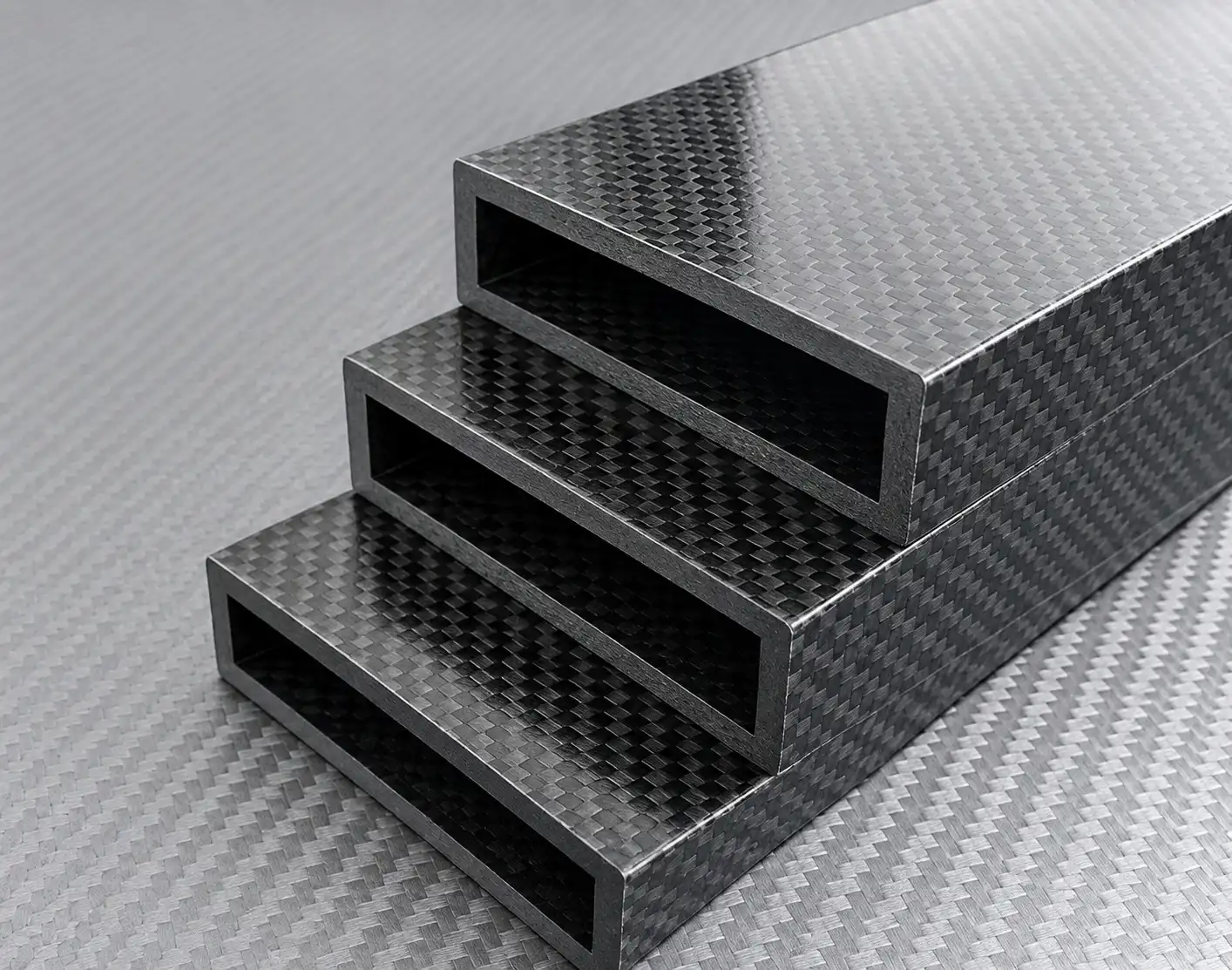
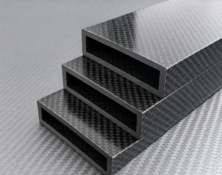
A Kohlefaser-Rechteckrohr is an effective structural option for rover robotic arms that need lower moving mass without sacrificing rigidity. Compared with traditional metal arm members, a properly designed carbon fiber rectangular tube can help reduce inertia at the joints, improve dynamic response, and provide a practical beam structure for mounting brackets, actuators, wiring, and end-effectors.
For university rover teams, research prototypes, industrial mobile robots, and competition manipulators, the goal is not simply to make the arm lighter. The structural tube must also resist bending, torsion, vibration, repeated loading, and local stresses created by bolts, clamps, inserts, and joint interfaces.
Why Rectangular Carbon Fiber Tubes?
A rectangular carbon fiber tube provides flat mounting surfaces and a directional structure that is well suited to robotic arm links. Unlike a round tube, which may require additional brackets or saddles for flat components, a rectangular profile can simplify the installation of motor mounts, gearbox plates, sensor housings, cable guides, and joint fixtures.
Key benefits include:
Lower structural mass for reduced joint torque demand
High stiffness-to-weight ratio for arm links and manipulator beams
Flat outer surfaces for brackets and mechanical interfaces
Internal space for cables, encoder wires, or pneumatic lines
Customizable width, height, wall thickness, and cut length
Optional machining, drilled holes, slots, and bonded end fittings
Matte, gloss, painted, or bonding-ready surface options
The greatest benefit appears when the tube is used farther from the robot joint. Weight at the end of a long arm has a larger effect on rotational inertia and motor demand than weight located near the base. By reducing the mass of the forearm or tool-support section, a carbon fiber rectangular tube can help improve arm acceleration, deceleration, and positional stability.
Verwandte Artikel:
Carbon Fiber Tube for UAV Antenna Placement & GNSS Design
Multi-Size Carbon Fiber Tube Order for a UAV Glider Build
Carbon Fiber Rectangular Tube for Lightweight Rover Robotic Arms
T800 Carbon Fiber Tube for Wind Tunnel Testing
Small Batch Carbon Fiber Pipe Orders: Can You Buy Just a Few Pieces?
Carbon Fiber Pipe Supplier vs Trading Company: What’s the Difference?
Structural Design for Rover Arms
A rover arm is exposed to more than static payload weight. During lifting, reaching, driving over uneven terrain, grabbing an object, or stopping suddenly, the arm can experience bending, torsion, vibration, and impact loads.
For this reason, a carbon fiber rectangular tube should be designed around the complete load case:
Maximum payload at the end effector
Arm length and joint locations
Peak motor torque and acceleration
Expected torsional loads from offset payloads
Allowable deflection at the gripper or tool
Repeated duty cycles and fatigue requirements
Outdoor exposure to dust, moisture, UV, and temperature changes
Installation loads from clamps, bolts, and end fittings
A typical robotic-arm laminate may use 0° unidirectional carbon fiber along the tube length to improve bending stiffness. Additional ±45° layers can increase torsional stability, while 90° layers help maintain the tube shape and improve resistance to local crushing around mounts or inserts.
This hybrid approach is important because a tube designed only for straight-line bending may not perform well when the arm experiences twisting loads or concentrated clamping pressure.
Selecting Tube Dimensions
A carbon fiber rectangular tube is usually specified by its outer width, outer height, wall thickness, length, corner radius, and dimensional tolerances.
For example, a tube specified as 80 × 40 × 3 mm has an outer width of 80 mm, an outer height of 40 mm, and a nominal wall thickness of 3 mm. Its approximate internal opening is 74 × 34 mm before considering corner radii and manufacturing tolerances.
When selecting the profile, the larger dimension should generally be oriented in the primary bending direction. If the arm mainly bends vertically under gravity and payload loading, positioning the taller side in that bending plane can improve stiffness. However, the best orientation depends on the actual arm geometry, joint layout, payload direction, and mounting arrangement.
Before ordering, purchasers should confirm:
Required outer and inner dimensions
Wall thickness and acceptable variation
Length tolerance and end-face squareness
Straightness and twist tolerance
Surface finish and visual requirements
Hole, slot, or CNC machining details
Structural load and deflection targets
Quantity, prototype needs, and spare-part requirements
For precision assemblies, the RFQ should identify the functional datum surfaces, corner radii, end condition, straightness, wall thickness, and any internal hardware or insert requirements. These details help prevent fit-up problems after delivery.
Connecting Carbon Fiber Tubes to Joints
The connection design is often the most important part of a carbon fiber robotic arm. A strong tube can still fail prematurely if bolts create excessive local pressure, holes are poorly positioned, or end fittings do not distribute the load correctly.
Common connection methods include:
Bonded aluminum, stainless steel, titanium, or polymer end inserts
Internal sleeve joints for joining or reinforcing tube ends
External clamping brackets for removable or adjustable assemblies
Through-bolts with sleeves, washers, and local reinforcement
Gusset plates for rectangular-tube frames and arm assemblies
Custom machined end fittings bonded into the tube
Hybrid connections combining adhesive bonding and mechanical retention
For rectangular tubes, bonded end inserts and gusset-style connecting plates are especially practical. An insert can provide a threaded mounting point or interface for a robotic joint without requiring threads to be cut directly into the composite wall. External clamps are useful where adjustability or rapid replacement is required, but they should use broad contact areas and rounded edges to avoid crushing the laminate.
Directly tightening a small metal clamp or bolt against a thin carbon fiber wall can create stress concentrations, cracking, delamination, or local crushing. Where mechanical fastening is required, the tube may need thicker walls, locally reinforced laminate zones, internal backing plates, or fitted sleeves.
Carbon Fiber and Aluminum Interfaces
Many rover arms combine a carbon fiber rectangular tube with aluminum joint plates, actuator brackets, or end fittings. This can be an efficient design, but it requires attention to material compatibility.
Carbon fiber is electrically conductive. When carbon fiber directly contacts aluminum in the presence of moisture, the aluminum may be vulnerable to galvanic corrosion. This risk is especially relevant for outdoor rover testing, humid storage, rain exposure, condensation, or joints where water and dirt can collect.
Recommended precautions include:
Use non-conductive isolation layers between carbon fiber and aluminum
Add fiberglass, polymer, rubber, or adhesive-film barriers
Use anodized, coated, or sealed aluminum components
Isolate metal fasteners with non-conductive sleeves or washers where appropriate
Seal exposed edges and joints against water ingress
Avoid joint geometries that trap water, mud, or cleaning fluid
Inspect coatings and interfaces regularly after field testing
Electrical isolation and moisture control are the primary methods for reducing galvanic corrosion risk in carbon fiber–aluminum assemblies. Insulating barriers, anodizing, protective coatings, sealants, and isolated fasteners can help break the electrical path and limit water penetration.
Manufacturing and Machining Options
Custom carbon fiber rectangular tubes can be supplied as raw cut lengths or as partially finished structural components. Depending on the project, the supplier may provide:
Custom width, height, wall thickness, and length
Pultruded or laminated tube construction
UD, ±45°, 90°, and woven-fabric hybrid layups
Matte or gloss carbon fiber finishes
CNC cut-to-length service
Drilled holes, slots, windows, and end milling
Bonding surface preparation
Pre-installed end inserts or reinforcement sleeves
Dimensional inspection reports and first-article samples
Carbon fiber machining requires appropriate tools, controlled feed rates, backing support, and dust extraction. Drilling or milling without proper support can cause fiber pullout, delamination, edge breakout, or damage to thin walls. Manufacturers should use composite-appropriate carbide or diamond tooling and inspect the machined hole edges and structural surfaces.
A Practical Material Solution
A custom carbon fiber rectangular tube can provide a lightweight, rigid, and adaptable structural platform for rover robotic arms. It is particularly useful when the project requires reduced joint loading, lower inertia, flat mounting surfaces, internal cable routing, and repeatable arm performance.
The best result comes from designing the tube, laminate, end fittings, mounting interfaces, and environmental protection as one system. By defining the load case and integration details before production, rover teams can turn a carbon fiber rectangular tube from a simple material purchase into a reliable arm-link solution for testing, competition, and future upgrades.