
 Polish
  English
  German
  Japanese
  Arabic
  Czech
Czech  Spanish
  French
  Italian
  Danish
  Portuguese
  Norwegian
  Dutch
Dutch 
Spis treści
A glider can look perfectly straight on the bench and still fly as if something is off. You launch, add a few clicks of elevator trim, and the model settles down. Then it picks up speed and needs a different setting again. After landing, the tail looks fine.
That kind of problem often starts in the back of the fuselage.
The tail boom holds the stabilizer or V-tail far behind the wing. A small change in its angle can change the way the tail meets the airflow. On a light thermal glider, you may only notice it during a fast dive. On a slope glider or F5J model, the change can show up much sooner.
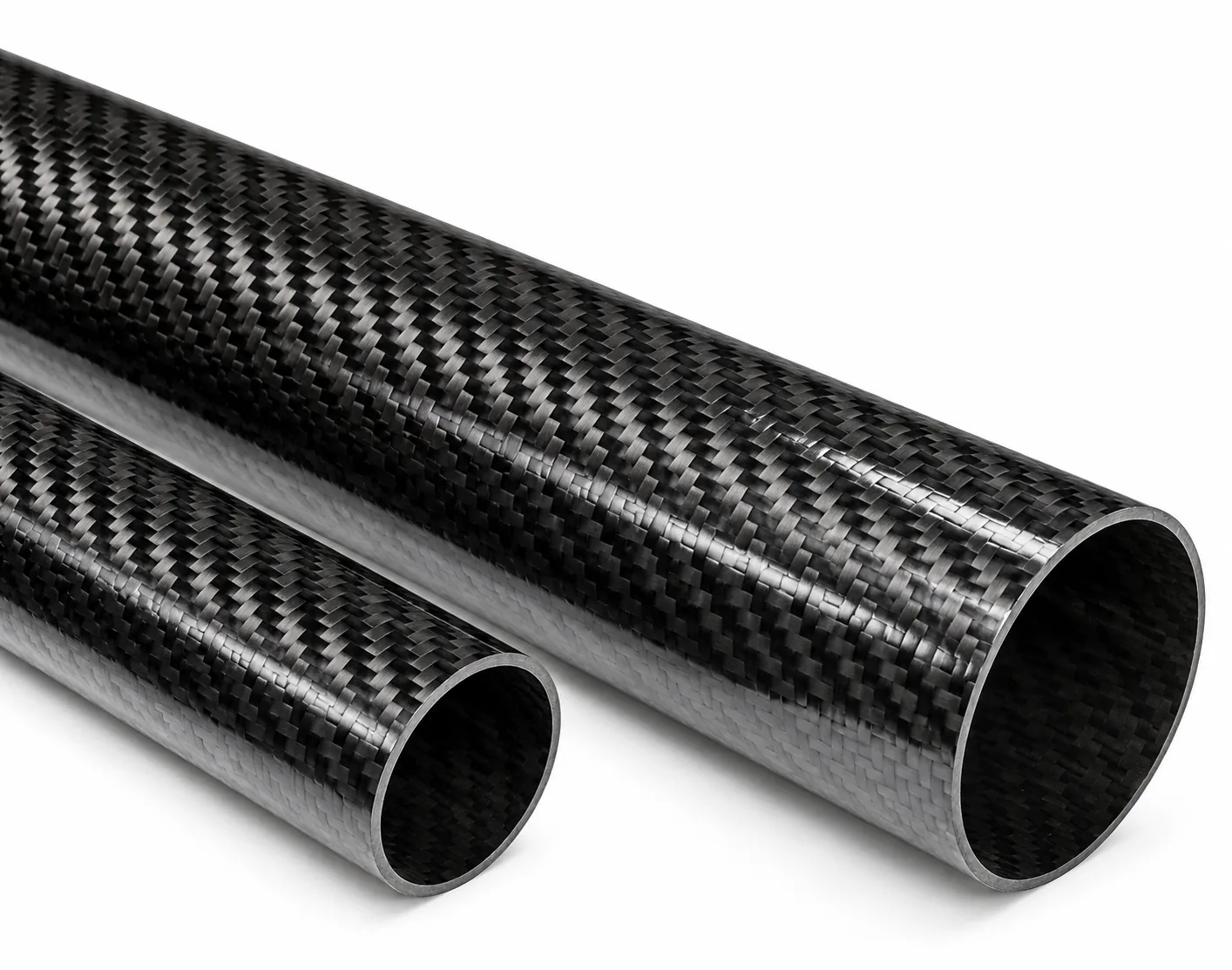
For this reason, carbon fiber tubes for glider projects should be selected for alignment and twist control, not only for low weight.
The Trim Problem May Be Mechanical
It is easy to blame the transmitter when a model needs repeated trim changes. Sometimes the radio setup is the cause. More often, the tail boom, tail mount, or pushrod system has moved slightly under load.
A weak boom can twist when the tail sees more air pressure. That twist may be too small to see by eye, but it can change the stabilizer angle enough to affect pitch. With a V-tail, one side may move differently from the other. The model can then show a mix of pitch, yaw, and roll that does not match the radio input.
Start with the simple checks:
Does the boom sit straight in the fuselage?
Does the tailplane sit square to the wing?
Does the V-tail have the same angle on both sides?
Does the tail mount move when you hold the fuselage and apply light force by hand?
Do both pushrods return to the same neutral position?
These checks take little time. They can save a lot of unnecessary radio adjustment.
Powiązane artykuły:
Carbon Fiber Tubes for Glider Tail Boom Alignment & Trim Control
Carbon Fiber Tube for UAV Antenna Placement & GNSS Design
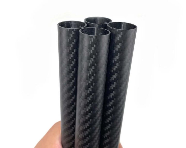
Multi-Size Carbon Fiber Tube Order for a UAV Glider Build
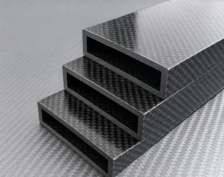
Carbon Fiber Rectangular Tube for Lightweight Rover Robotic Arms
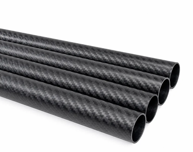
T800 Carbon Fiber Tube for Wind Tunnel Testing
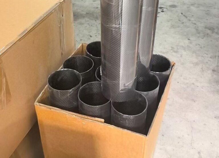
Small Batch Carbon Fiber Pipe Orders: Can You Buy Just a Few Pieces?
Tube Shape Matters More Than It Seems
A straight round tube works well for many sport gliders. It is easy to source, easy to bond, and simple to inspect. But a tube that feels stiff in your hand may still twist during a fast pass.
The tube needs to handle two different jobs. It must resist bending from the tail load, and it must resist twist from the stabilizer, rudder, or V-tail. A tube built mainly with fibers running along its length can be good in bending but less effective against torsion.
That is why the layup matters. Long 0° fibers support bending along the boom. ±45° fibers help the tube resist twisting. Hoop layers help the tube keep its shape around mounting points and bonded areas.
A tapered boom is often useful when the glider needs more strength near the fuselage but less weight near the tail. The larger end gives the fuselage joint more bonding area. The smaller end keeps weight out of the rear of the model, where every extra gram makes CG adjustment harder.
Some commercial carbon tail booms are specifically built for torsional, flexural, and hoop stiffness rather than only appearance. That is the right way to think about carbon fiber tubes for glider tail sections.
A Good Tail Mount Needs a Jig
A stiff tail boom will not fix a tail that was bonded on at the wrong angle.
This is common with V-tail models. The two tail panels may look close enough during assembly, but a small difference in angle can create uneven control response. The model may need rudder trim in one flight mode and elevator trim in another. A conventional horizontal stabilizer has the same problem when its incidence does not match the wing.
Use a simple jig when bonding the tail. It does not need to be expensive. The goal is to hold the boom, wing reference line, and tail surfaces in the right position while the adhesive cures.
Before bonding, lightly sand the glossy surface where the mount will sit. Clean away dust and use an adhesive system suited to composites. A close-fitting saddle or sleeve spreads the load over a wider area. A tiny screw pressed into a thin tube wall does not.
If the tail must be removable, add a locating feature. This might be a sleeve, shallow keyway, anti-rotation pin, or reinforced mounting block. The tail should return to the same position after transport and reassembly.
Pushrods Can Change the Feel of the Tail
The boom may be straight, yet the control system inside it can still cause trim trouble.
A long pushrod under compression can bend. A guide tube may rub against the carbon wall. A wire can catch on a servo lead. In a V-tail, two pushrods may touch each other inside a narrow boom. Each problem adds lost motion or changes where the surface returns after a control input.
Keep the pushrod run as straight as possible. Use guide tubes or PTFE liners when needed, but do not add so many supports that friction becomes the next problem. The pushrod needs enough support to avoid flex, especially when pushing the elevator or rudder.
Some DLG builders use a fully supported carbon rod or stainless-steel wire inside a properly sized Teflon tube. The guide tube is bonded along the boom length so the linkage stays straight and does not flex under load.
When ordering carbon fiber tubes for glider control systems, check the ID as carefully as the OD. The boom must have room for pushrods, guide tubes, wire routing, and tail hardware.
Check the Boom Before the First Flight
Do not wait for flight trim to reveal an alignment problem.
When the tube arrives, inspect the ends, surface, and straightness. Roll it on a flat surface or support it in a simple fixture. Look for visible runout, deep scratches, crushed areas, soft spots, or cracks near the ends.
After assembly, sight along the fuselage from the nose toward the tail. Compare the wing centerline with the boom centerline. Check the stabilizer angle with a simple incidence gauge if you have one. Then move the controls slowly from end to end. The pushrods should not bind, scrape, or move sideways inside the boom.
A hard landing deserves another inspection. Carbon fiber can hide damage. The outer surface may look normal while the laminate inside has started to separate. If a boom needs repair, an internal sleeve should taper its stiffness transition instead of ending abruptly at the break. A sharp sleeve edge can create a new failure point beside the repair.
Carbon Fiber Tubes for Gliders
Find answers about RC glider trim, tail boom stiffness, carbon fiber layups, drilling, repairs, and how tube design affects flight performance.
01
Why does my RC glider need different trim at different speeds?
The tail boom may twist as air load rises. The tail mount can also shift, or a long pushrod may flex under compression. Check the boom, tailplane angle, and linkage before changing the transmitter setup.
02
Is a larger tail boom always better?
No. A larger tube may be stiffer, but it also adds weight behind the CG. A tapered tube often gives a better balance because it keeps more material near the fuselage and less material near the tail.
03
What carbon fiber layup works well for a tail boom?
A mixed layup usually works best. Long UD fibers help with bending. ±45° layers help the boom resist twist. Hoop layers support the tube shape and mounting areas. The right balance depends on boom length, tail size, flight speed, and launch loads.
04
Can I drill a carbon fiber tail boom?
Yes, but drill only where needed. Support the tube during drilling, use a suitable composite drill, and clean the hole edges. Thin-wall tubes may need a sleeve or local reinforcement around bolts and tail mounts.
05
Can I repair a cracked tail boom?
Small damage can sometimes be repaired with an internal sleeve and external carbon reinforcement. The repaired area must stay straight and should have a gradual stiffness change. Replace the boom when it is crushed, badly cracked, or damaged near the fuselage or tail mount.