
 Czech
Czech  English
  German
  Japanese
  Arabic
  Spanish
  French
  Italian
  Danish
  Polish
  Portuguese
  Norwegian
  Dutch
Dutch 
Obsah
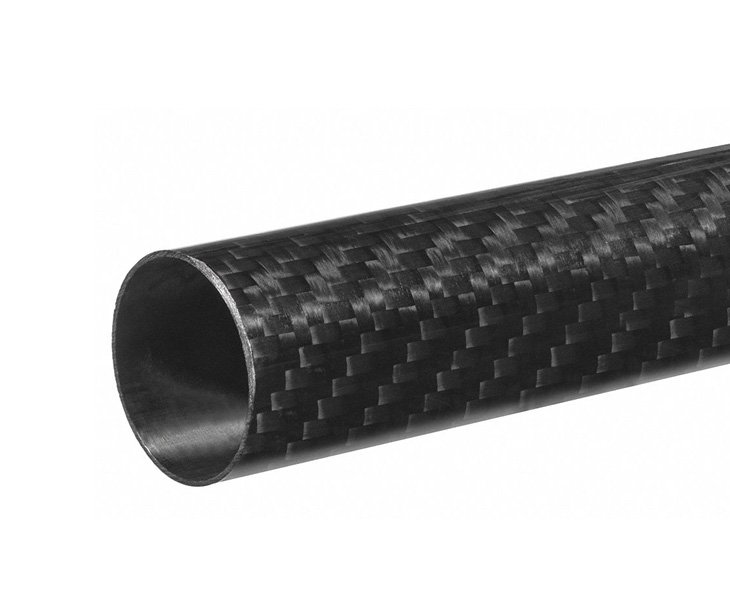
A carbon fiber tube for UAV can reduce structural weight and increase airframe stiffness, but it also affects antenna integration. Carbon fiber reinforced polymer is electrically conductive and may reflect, absorb, or alter radio-frequency signals depending on the tube layup, diameter, antenna type, frequency band, and installation position.
For UAV manufacturers, antenna placement should therefore be considered at the same time as carbon fiber tube selection. A lightweight airframe is only useful when GNSS, GPS, telemetry, RC control, video transmission, and payload communications remain reliable throughout flight.
Why Carbon Fiber Tubes Affect RF Performance
Carbon fiber tubes are widely used for UAV arms, booms, fuselages, landing structures, wing spars, and payload supports. Their high stiffness-to-weight ratio makes them suitable for aerial platforms that need long endurance, stable flight, and reduced structural mass.
However, carbon fiber is not RF-transparent in the same way as fiberglass, nylon, or many engineering plastics. A carbon fiber tube located close to an antenna may affect antenna impedance, radiation direction, gain, and reception quality. The result can be reduced GNSS signal strength, inconsistent telemetry range, lower video-link reliability, or changes in antenna performance when the UAV changes attitude.
The impact is not identical in every project. A small tube located far from an antenna may have limited effect, while a large carbon fiber fuselage tube positioned directly below or beside a GNSS antenna can create a more significant problem. Carbon fiber layup also matters because fiber orientation and conductive paths influence how the structure interacts with electromagnetic energy. Carbon-fiber UAV frames can absorb, reflect, or alter electromagnetic signals, so antenna performance should be verified on the finished airframe rather than assumed from bench testing alone.
Související články:
Carbon Fiber Tube for UAV Antenna Placement & GNSS Design
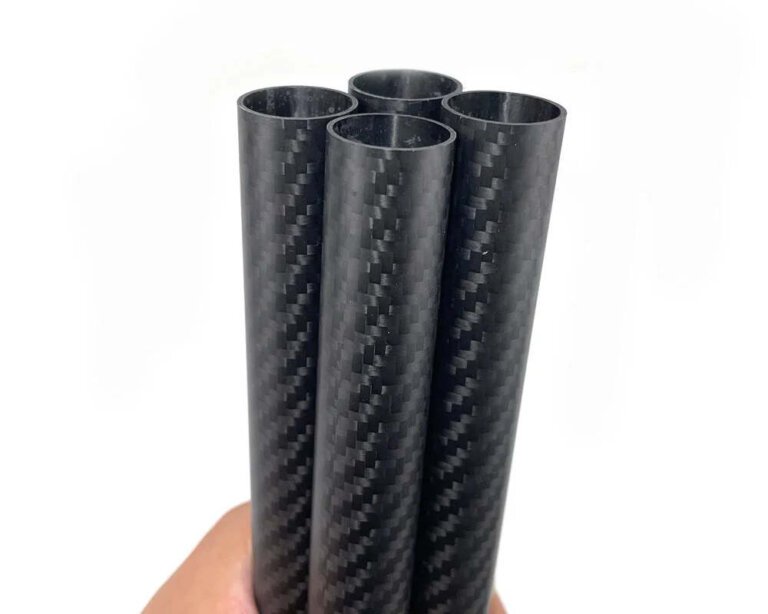
Multi-Size Carbon Fiber Tube Order for a UAV Glider Build
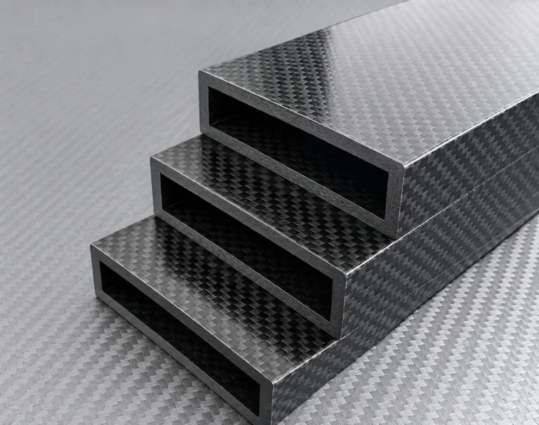
Carbon Fiber Rectangular Tube for Lightweight Rover Robotic Arms
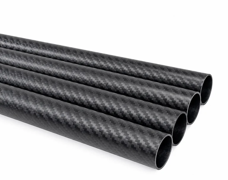
T800 Carbon Fiber Tube for Wind Tunnel Testing
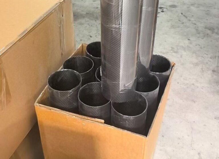
Small Batch Carbon Fiber Pipe Orders: Can You Buy Just a Few Pieces?
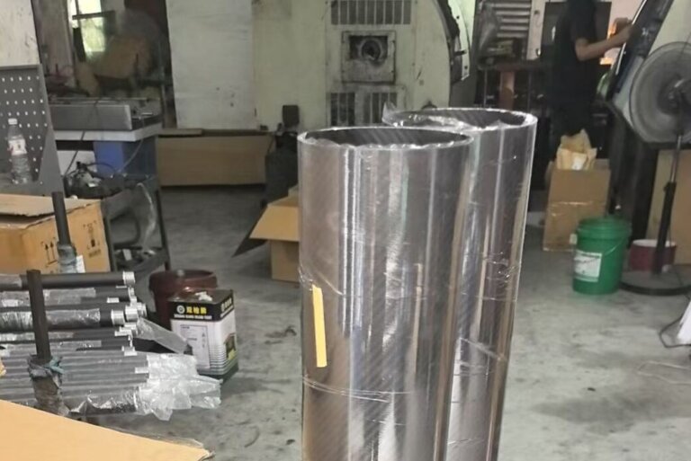
Carbon Fiber Pipe Supplier vs Trading Company: What’s the Difference?
GNSS and GPS Antenna Placement Above Carbon Fiber Frames
For GPS, GNSS, RTK, and navigation antennas, the preferred position is usually high on the UAV, with an open view of the sky and separation from carbon fiber structure, propulsion electronics, and transmitting antennas.
A practical design approach is to mount the GNSS antenna above the main carbon fiber tube or frame using a non-conductive standoff. Nylon, fiberglass, FR4/G10, or other insulated materials can help create physical separation between the antenna and the carbon fiber structure.
Key considerations include:
Place the GNSS antenna above the carbon fiber frame whenever possible
Maintain a clear sky view around the antenna
Avoid mounting the antenna directly onto a carbon fiber tube or plate
Keep GNSS antennas away from motors, ESCs, battery leads, and DC-DC converters
Use a stable non-conductive mast or mounting plate
Protect the antenna from propeller wash and mechanical vibration
Verify performance with the final battery, payload, and propulsion system installed
There is no single correct mounting height for every UAV. The required spacing depends on the antenna design, UAV size, carbon fiber tube geometry, nearby electronics, and intended operating environment. GNSS integration guidance commonly recommends using insulated standoffs and a dedicated ground plane instead of relying on the carbon fiber structure itself.
Telemetry, Video and RC Antenna Separation
A UAV may carry several radio systems at the same time: GNSS navigation, RC control, telemetry, video transmission, payload data links, and sometimes cellular or satellite communication modules. Even when these systems use different frequencies, poor physical placement can reduce signal reliability.
Telemetry and receiver antennas should not be routed tightly against carbon fiber tubes for long distances. They should also be separated from high-current battery cables, ESCs, motor phase wires, VTX units, and switching power supplies. These components can create electrical noise that affects reception and signal quality.
For carbon fiber UAV frames, a good layout usually includes:
Separate GNSS antennas from high-power video transmitters
Keep receiver antennas away from carbon fiber tube shadows
Route RF cables away from high-current power wiring
Avoid long parallel runs between coaxial cable and motor power cables
Secure antenna cables to prevent vibration damage and connector fatigue
Use different antenna orientations where diversity reception is required
Test signal quality with motors stopped and running
Proper antenna placement and grounding are important because onboard electronics and propulsion systems can create electromagnetic interference that affects UAV navigation and communications.
Ground Planes, Insulated Mounts and Cable Routing
A common misunderstanding is that carbon fiber can automatically function as a suitable antenna ground plane because it is conductive. In practice, carbon fiber is not a uniform metal sheet. Its conductivity varies with fiber direction, laminate design, resin content, and surface treatment. It should not be treated as a predictable RF ground plane for a GPS or GNSS antenna.
Where a ground plane is required, a dedicated conductive surface such as an aluminum plate, copper-clad PCB, or properly designed metal ground plane is generally more controllable. The antenna can then be installed on a non-conductive mount above the carbon fiber tube structure.
For cable routing, keep GNSS coaxial cables short, avoid unnecessary adapters, and protect cables from sharp bends, vibration, and abrasion at tube-entry points. If cables pass through a carbon fiber tube, use grommets or protective sleeves at drilled holes. Avoid placing antenna coaxial cables directly alongside battery cables and motor wiring for long distances.
For custom carbon fiber tube projects, it is useful to define cable-routing requirements before production. A supplier may be able to support cut lengths, internal routing space, protective end treatment, CNC holes, slots, bonding surfaces, or mounting features for antenna brackets.
Validating Antenna Performance After Integration
Antenna placement should be validated after the carbon fiber tube, flight electronics, battery, propulsion system, and payload have all been installed. A GPS module that performs well on a workbench may behave differently once it is mounted near a carbon fiber airframe, active motors, and transmitting equipment.
A practical validation plan should record:
GNSS satellite count
Carrier-to-noise density ratio, C/N0C/N_0C/N0
Time to first fix
HDOP and PDOP values
RTK fixed status, where applicable
Telemetry RSSI and packet-loss rate
Video-link stability
Signal performance with motors off and at operating throttle
Signal behavior during hovering, turns, climbs, and distance flights
If performance declines after final assembly, review antenna height, distance from carbon fiber tubes, ground-plane design, cable routing, power-system noise, and separation from video or telemetry transmitters. Final antenna locations, standoff dimensions, cable-routing paths, and mounting instructions should be documented before UAV production begins. Proper real-world testing is essential because RF performance depends on the complete airframe, not only on an individual carbon fiber tube.
FAQ
Does a carbon fiber tube block GPS or GNSS signals?
A carbon fiber tube can affect GPS or GNSS reception when it is close to the antenna or placed in the antenna’s signal path. The level of impact depends on the tube’s geometry, laminate, antenna type, frequency, and installation position. Use a raised, insulated mount and validate the final UAV assembly.
Can I mount a GPS antenna directly on a carbon fiber UAV frame?
Direct mounting is generally not recommended. A non-conductive mast or standoff is usually preferred to separate the antenna from the carbon fiber structure. A dedicated metal or copper-clad PCB ground plane may also be needed, depending on the antenna design.
Can a carbon fiber tube be used as a UAV antenna mast?
It can provide structural support, but fiberglass or another non-conductive material is usually a safer choice for GNSS/GPS antenna masts. If carbon fiber must be used, increase the separation distance and verify antenna performance through ground and flight testing.
What should be tested after antenna installation?
Test satellite reception, C/N0C/N_0C/N0, GNSS fix performance, telemetry RSSI, packet loss, video stability, and behavior with motors both off and running. Flight tests should include hover, maneuvering, full-power operation, and representative mission conditions.
A custom carbon fiber tube for UAV should be designed as part of the entire airframe system. By considering antenna location, insulated mounts, cable routing, RF separation, and validation testing early in the design process, UAV manufacturers can retain the lightweight and high-stiffness benefits of carbon fiber while protecting reliable navigation and communication performance.