
 Hebrew
 English
 German
 Czech
 Spanish
 French
 Danish
 Portuguese
 Norwegian
 Dutch
תוכן עניינים
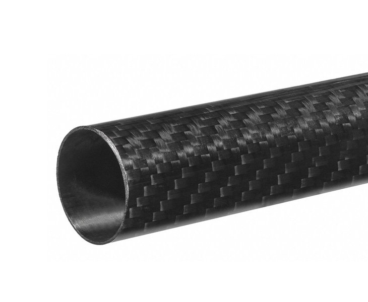
A צינור סיבי פחמן עבור כטב״ם יכול להפחית את משקל המבנה ולהגביר את קשיחות שלדת האוויר, אך הוא גם משפיע על שילוב האנטנה. פולימר מחוזק בסיבי פחמן מוליך חשמלית ועלול להחזיר, לספוג או לשנות אותות בתדר רדיו בהתאם למבנה השכבות של הצינור, לקוטרו, לסוג האנטנה, לפס התדרים ולמיקום ההתקנה.
לפיכך, עבור יצרני כטב״מים, יש לשקול את מיקום האנטנה במקביל לבחירת צינור סיבי הפחמן. שלדת אוויר קלה שימושית רק כאשר GNSS, GPS, טלמטריה, שליטת RC, שידור וידאו ותקשורת מטען ייעודי נשארים אמינים לאורך כל הטיסה.
מדוע צינורות סיבי פחמן משפיעים על ביצועי RF
צינורות סיבי פחמן נמצאים בשימוש נרחב בזרועות כטב״ם, בבומים, בגופי כלי טיס, במבני נחיתה, בקורות כנף ובתמיכות מטען ייעודי. יחס הקשיחות למשקל הגבוה שלהם הופך אותם מתאימים לפלטפורמות אוויריות הנדרשות לאורך טיסה ממושך, לטיסה יציבה ולהפחתת מסת המבנה.
עם זאת, סיבי פחמן אינם שקופים ל-RF באותו אופן כמו פיברגלס, ניילון או פלסטיקים הנדסיים רבים. צינור סיבי פחמן הממוקם קרוב לאנטנה עלול להשפיע על עכבת האנטנה, על כיוון הקרינה, על ההגבר ועל איכות הקליטה. התוצאה עשויה להיות ירידה בחוזק אות GNSS, טווח טלמטריה לא עקבי, אמינות נמוכה יותר של קישור הווידאו, או שינויים בביצועי האנטנה כאשר הכטב״ם משנה מנח.
ההשפעה אינה זהה בכל פרויקט. צינור קטן הממוקם הרחק מאנטנה עשוי להשפיע באופן מוגבל, ואילו צינור גוף גדול מסיבי פחמן הממוקם ישירות מתחת לאנטנת GNSS או לצדה עלול ליצור בעיה משמעותית יותר. גם מבנה השכבות של סיבי הפחמן חשוב, משום שכיוון הסיבים ונתיבים מוליכים משפיעים על האופן שבו המבנה מתקשר עם אנרגיה אלקטרומגנטית. מסגרות כטב״ם מסיבי פחמן עלולות לספוג, להחזיר או לשנות אותות אלקטרומגנטיים, ולכן יש לאמת את ביצועי האנטנה על שלדת האוויר המוגמרת ולא להניח אותם על סמך בדיקות ספסל בלבד.
מאמרים קשורים:
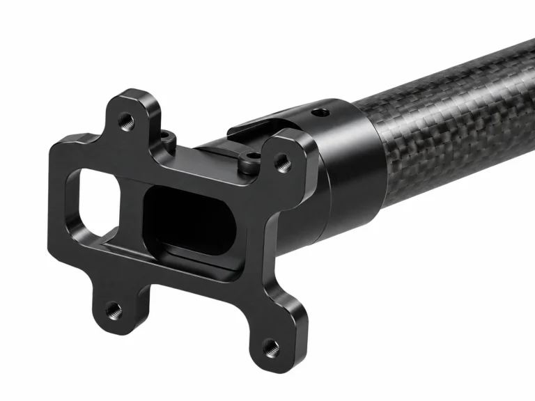
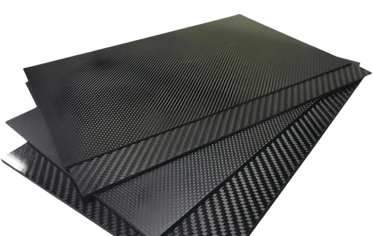
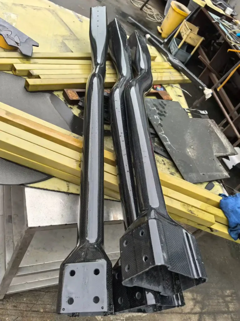
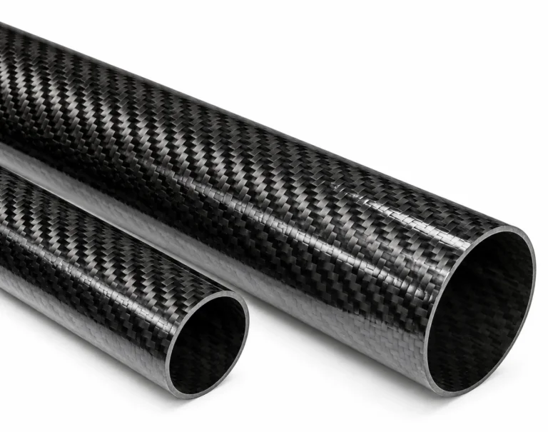
הצבת אנטנות GNSS ו-GPS מעל מסגרות סיבי פחמן
עבור אנטנות GPS, GNSS, RTK וניווט, המיקום המועדף הוא בדרך כלל גבוה בכטב״ם, עם שדה ראייה פתוח לשמיים והפרדה ממבנה סיבי פחמן, מאלקטרוניקת הנעה ומאנטנות משדרות.
גישה תכנונית מעשית היא להתקין את אנטנת ה-GNSS מעל צינור סיבי הפחמן הראשי או המסגרת, באמצעות מרווח מבודד לא-מוליך. ניילון, פיברגלס, FR4/G10 או חומרים מבודדים אחרים יכולים לסייע ביצירת הפרדה פיזית בין האנטנה למבנה סיבי הפחמן.
שיקולים מרכזיים כוללים:
להציב את אנטנת ה-GNSS מעל מסגרת סיבי הפחמן בכל עת שהדבר אפשרי
לשמור על שדה ראייה פנוי לשמיים סביב האנטנה
להימנע מהתקנת האנטנה ישירות על צינור או לוחית מסיבי פחמן
להרחיק אנטנות GNSS ממנועים, בקרי ESC, כבלי סוללה וממירי DC-DC
להשתמש בתורן או בלוחית התקנה יציבים ולא-מוליכים
להגן על האנטנה מפני שטיפת מדחפים ומרעידות מכניות
לאמת את הביצועים כאשר הסוללה, המטען הייעודי ומערכת ההנעה הסופיים מותקנים
There is no single correct mounting height for every UAV. The required spacing depends on the antenna design, UAV size, carbon fiber tube geometry, nearby electronics, and intended operating environment. GNSS integration guidance commonly recommends using insulated standoffs and a dedicated ground plane instead of relying on the carbon fiber structure itself.
Telemetry, Video and RC Antenna Separation
A UAV may carry several radio systems at the same time: GNSS navigation, RC control, telemetry, video transmission, payload data links, and sometimes cellular or satellite communication modules. Even when these systems use different frequencies, poor physical placement can reduce signal reliability.
Telemetry and receiver antennas should not be routed tightly against carbon fiber tubes for long distances. They should also be separated from high-current battery cables, ESCs, motor phase wires, VTX units, and switching power supplies. These components can create electrical noise that affects reception and signal quality.
For carbon fiber UAV frames, a good layout usually includes:
Separate GNSS antennas from high-power video transmitters
Keep receiver antennas away from carbon fiber tube shadows
Route RF cables away from high-current power wiring
Avoid long parallel runs between coaxial cable and motor power cables
Secure antenna cables to prevent vibration damage and connector fatigue
Use different antenna orientations where diversity reception is required
Test signal quality with motors stopped and running
Proper antenna placement and grounding are important because onboard electronics and propulsion systems can create electromagnetic interference that affects UAV navigation and communications.
Ground Planes, Insulated Mounts and Cable Routing
A common misunderstanding is that carbon fiber can automatically function as a suitable antenna ground plane because it is conductive. In practice, carbon fiber is not a uniform metal sheet. Its conductivity varies with fiber direction, laminate design, resin content, and surface treatment. It should not be treated as a predictable RF ground plane for a GPS or GNSS antenna.
Where a ground plane is required, a dedicated conductive surface such as an aluminum plate, copper-clad PCB, or properly designed metal ground plane is generally more controllable. The antenna can then be installed on a non-conductive mount above the carbon fiber tube structure.
For cable routing, keep GNSS coaxial cables short, avoid unnecessary adapters, and protect cables from sharp bends, vibration, and abrasion at tube-entry points. If cables pass through a carbon fiber tube, use grommets or protective sleeves at drilled holes. Avoid placing antenna coaxial cables directly alongside battery cables and motor wiring for long distances.
For custom carbon fiber tube projects, it is useful to define cable-routing requirements before production. A supplier may be able to support cut lengths, internal routing space, protective end treatment, CNC holes, slots, bonding surfaces, or mounting features for antenna brackets.
Validating Antenna Performance After Integration
Antenna placement should be validated after the carbon fiber tube, flight electronics, battery, propulsion system, and payload have all been installed. A GPS module that performs well on a workbench may behave differently once it is mounted near a carbon fiber airframe, active motors, and transmitting equipment.
A practical validation plan should record:
GNSS satellite count
Carrier-to-noise density ratio, C/N0C/N_0C/N0
Time to first fix
HDOP and PDOP values
RTK fixed status, where applicable
Telemetry RSSI and packet-loss rate
Video-link stability
Signal performance with motors off and at operating throttle
Signal behavior during hovering, turns, climbs, and distance flights
If performance declines after final assembly, review antenna height, distance from carbon fiber tubes, ground-plane design, cable routing, power-system noise, and separation from video or telemetry transmitters. Final antenna locations, standoff dimensions, cable-routing paths, and mounting instructions should be documented before UAV production begins. Proper real-world testing is essential because RF performance depends on the complete airframe, not only on an individual carbon fiber tube.
FAQ
Does a carbon fiber tube block GPS or GNSS signals?
A carbon fiber tube can affect GPS or GNSS reception when it is close to the antenna or placed in the antenna’s signal path. The level of impact depends on the tube’s geometry, laminate, antenna type, frequency, and installation position. Use a raised, insulated mount and validate the final UAV assembly.
Can I mount a GPS antenna directly on a carbon fiber UAV frame?
Direct mounting is generally not recommended. A non-conductive mast or standoff is usually preferred to separate the antenna from the carbon fiber structure. A dedicated metal or copper-clad PCB ground plane may also be needed, depending on the antenna design.
Can a carbon fiber tube be used as a UAV antenna mast?
It can provide structural support, but fiberglass or another non-conductive material is usually a safer choice for GNSS/GPS antenna masts. If carbon fiber must be used, increase the separation distance and verify antenna performance through ground and flight testing.
What should be tested after antenna installation?
Test satellite reception, C/N0C/N_0C/N0, GNSS fix performance, telemetry RSSI, packet loss, video stability, and behavior with motors both off and running. Flight tests should include hover, maneuvering, full-power operation, and representative mission conditions.
A custom צינור סיבי פחמן עבור כטב״ם should be designed as part of the entire airframe system. By considering antenna location, insulated mounts, cable routing, RF separation, and validation testing early in the design process, UAV manufacturers can retain the lightweight and high-stiffness benefits of carbon fiber while protecting reliable navigation and communication performance.