 French
 English
 German
 Czech
 Spanish
 Hebrew
 Danish
 Portuguese
 Norwegian
 Dutch
Table des matières
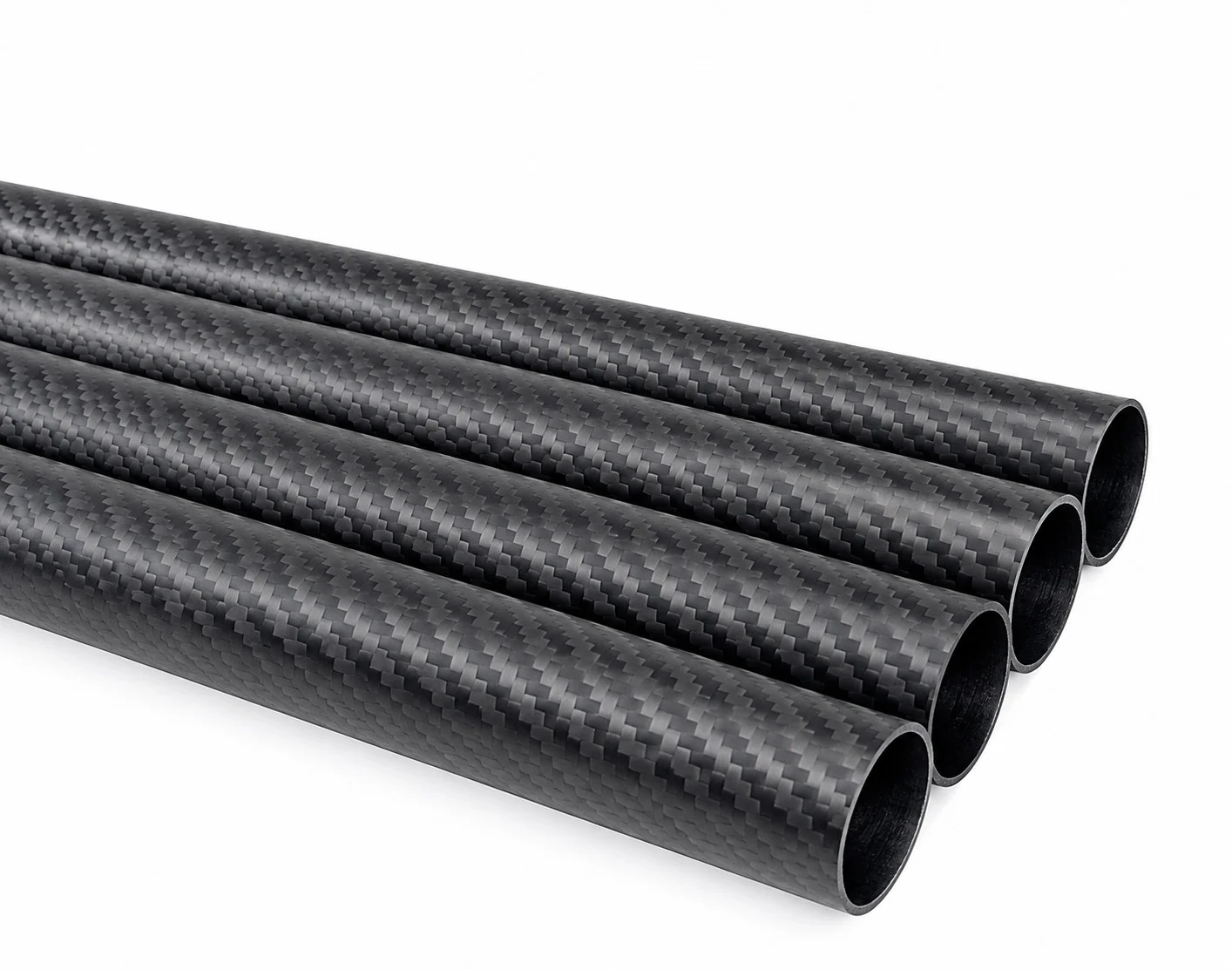
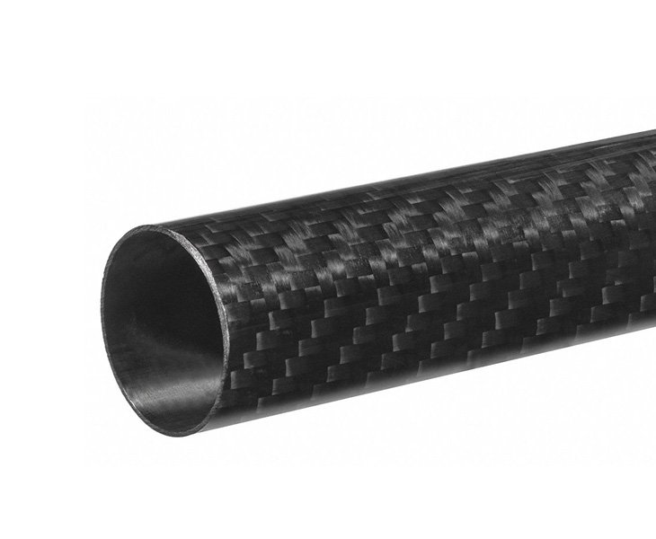
A Tube en fibre de carbone T800 constitue une solution structurelle légère efficace pour les applications de support de modèles en soufflerie qui exigent une rigidité élevée, une faible déformation et des performances stables sous charge aérodynamique. Pour les essais en soufflerie sur bâtiments à l’échelle, un tube sur mesure enroulé Tube en fibre de carbone T800 peut servir de mât de support rigide en porte-à-faux, également appelé sting, supportant un modèle en PLA ou un autre modèle léger tout en minimisant les vibrations indésirables.
Ce type de projet nécessite plus que le choix d’une nuance de fibre de carbone résistante. La performance finale du support dépend du diamètre du tube, de l’épaisseur de paroi, de la longueur non supportée, de l’orientation du stratifié, des conditions de fixation, du poids du modèle et de l’environnement d’essai aérodynamique.
Exigences du projet
Un client avait besoin d’un tube rond en fibre de carbone pour l’utiliser comme mât de support à base fixe dans des essais aérodynamiques à haute fréquence sur des modèles de bâtiments à l’échelle 1:400.
Les exigences proposées pour le tube comprenaient :
Application : support pour essais en soufflerie de modèles de bâtiments à l’échelle
Condition de support : fixation rigide à la base, le modèle étant monté au sommet
Longueur du tube : 15–30 po / 381–762 mm
Diamètre du tube : 2–3 po / 50,8–76,2 mm
Épaisseur de paroi : 1/16–1/8 po / environ 1,6–3,2 mm
Exigence de surface : finition mate pour une installation par ajustement par friction
Concept de structure : couches internes unidirectionnelles avec une couche externe en tissu sergé
Priorité : rigidité en flexion élevée et faibles vibrations
Étant donné que le tube fonctionne en porte-à-faux, son extrémité d’encastrement supporte le moment de flexion le plus élevé. Le tube doit rester suffisamment rigide pour empêcher tout déplacement visible du modèle de bâtiment pendant les essais en soufflerie, tout en restant suffisamment léger pour réduire les charges inutiles sur le montage et éviter une interférence excessive avec l’installation d’essai.
Articles connexes :
Comment évaluer le contrôle qualité des composants de drones en fibre de carbone
Comment vérifier les dimensions des tubes en fibre de carbone pour UAV
Feuilles CFRP pour équipements extérieurs : UV, humidité et vieillissement à long terme
Plaques en fibre de carbone pour cadres : prévenir le gauchissement après CNC
Tubes en fibre de carbone pour l'alignement de la poutre de queue et le contrôle de l'assiette d'un planeur
Tube en fibre de carbone pour le positionnement d'antenne UAV et la conception GNSS
Pourquoi les applications de sting en soufflerie exigent plus que des tubes standard
Dans les essais en soufflerie, le tube qui maintient un modèle à l’échelle est souvent appelé un “ sting ”. Sa fonction semble simple — maintenir le modèle en place — mais les exigences sont plus strictes qu’elles n’y paraissent. Il doit résister à la flexion sous charge aérodynamique, éviter de se déformer suffisamment pour fausser les données de position et rester à l’écart de sa propre fréquence de résonance pendant les essais à haute fréquence. Un tube simplement “ résistant ” n’est pas automatiquement adapté ici ; ce qui compte le plus, ce sont la rigidité et le comportement vibratoire, et pas seulement la charge qu’il peut supporter avant de rompre.
This is where a general-purpose carbon fiber tube and a properly specced T800 carbon fiber tube start to diverge.
Why Choose a T800 Carbon Fiber Tube?
T800 carbon fiber is commonly selected for high-performance composite structures because it offers higher stiffness than standard-modulus carbon fiber grades. It is suitable for applications where weight reduction and bending resistance are both important, including aerospace components, drone structures, precision test fixtures, robotic arms, and wind tunnel support systems.
For a wind tunnel sting application, a T800 carbon fiber tube may provide several advantages:
High specific stiffness for long unsupported support structures
Lower structural weight than steel or aluminum support members
Good fatigue resistance for repeated test cycles
Low thermal expansion compared with many metal alternatives
Customizable layup for axial stiffness, torsional stability, and local reinforcement
Clean carbon fiber appearance with matte or gloss finishing options
However, T800 alone does not guarantee that a tube will meet the stiffness target. A well-engineered laminate design is equally important. In many applications, the combination of T800 fiber, a sufficiently large outer diameter, and a predominantly axial UD layup is more important than simply increasing wall thickness.
Where T800 Fits in the Fiber Grade Lineup
T800 sits between T700 and T1000 in Toray’s fiber family, and it’s a common choice when a project needs a meaningful jump in strength over standard-modulus fibers without moving to the higher cost of T1000. For sting applications specifically, it’s worth being clear about what T800 actually improves: tensile strength gains are more significant than stiffness gains. If the strut’s main failure risk is bending or vibration rather than snapping under tension, wall thickness, layup structure, and tube geometry usually matter more than jumping to a higher fiber grade. A well-designed T800 carbon fiber tube can outperform a poorly laid-up T1000 tube in exactly this kind of stiffness-critical use case.
Recommended Tube Construction
For a high-stiffness carbon fiber tube used as a wind tunnel model support, a roll-wrapped construction is recommended. Roll-wrapped tubes allow the laminate structure to be tailored according to the loading direction and fixture requirements.
A practical hybrid layup may include:
0° unidirectional carbon fiber layers as the main structural layers for bending stiffness along the tube length
90° hoop layers to improve circularity, crushing resistance, and radial stability
±45° reinforcement layers to improve torsional performance and resistance to off-axis loads
3K 2×2 twill carbon fiber outer layer for surface quality, machining stability, and a professional carbon fiber appearance
The internal UD carbon fiber layers carry most of the longitudinal bending load. Since the building model is mounted at the top of a fixed-base tube, the support behaves similarly to a cantilever beam. Axial fiber orientation is therefore critical for reducing deflection.
The twill outer layer is not only decorative. It can provide a consistent outer surface, improve handling during production, and support a matte finish that is better suited to friction-fit assembly than a high-gloss surface.
Wall Thickness and Length Considerations
The requested wall thickness range of 1/16–1/8 in is feasible for many custom carbon fiber tubes. However, the correct wall thickness should be determined by the final load case.
A 15 in tube and a 30 in tube may have the same diameter and wall thickness, but the longer tube will deflect much more under the same top load. In cantilever applications, deflection increases rapidly as unsupported length increases.
For this reason, the 30 in version should be evaluated as the critical design condition. Depending on the building model weight, wind speed, and acceptable movement at the model top, the tube may require:
A higher percentage of 0° T800 UD layers
A larger outer diameter within the 2–3 in range
A wall thickness closer to 1/8 in
Local reinforcement at the fixed base
Reinforced mounting zones at the model interface
For applications with a strict vibration requirement, the design should also consider the tube’s natural frequency. A stiffer and lighter structure generally helps raise the natural frequency and reduce the risk of resonance during high-frequency aerodynamic testing.
Sizing for Stiffness: Diameter, Wall Thickness, and Length Together
A tube spec rarely stands on wall thickness alone — diameter, wall thickness, and length all interact. A strut in the 2–3 inch diameter range with a 1/16″ to 1/8″ wall, running 15 to 30 inches long, sits in a length-to-diameter ratio where stiffness and buckling resistance both need attention, not just tensile strength. Thicker walls add stiffness but also add weight and cost, which matters when the tube is mounted on precision test equipment. The right answer usually comes from matching wall thickness to the actual span and mounting condition, rather than defaulting to the thickest option in the tolerance range.
Getting From Spec Sheet to Sample
Custom sting tubes like this typically don’t come off a standard catalog page — diameter, wall thickness, layup combination, and finish all need to be confirmed against the specific test setup before production starts. Roll-wrapped hybrid layups (unidirectional plus twill) can be produced in small batches for testing and validation before committing to a larger order, which is usually the right way to confirm stiffness and fit before scaling up.
Options de personnalisation
A custom T800 carbon fiber tube can be produced with tailored structural and cosmetic specifications, including:
T700, T800, or hybrid carbon fiber material options
Round tube OD and ID customization
Wall thickness from approximately 1.6 mm to 3.2 mm or higher
Lengths from 15–30 in, with CNC cut-to-length service
UD, hoop, ±45°, and twill hybrid laminate structures
3K twill matte surface finish
Root-end reinforcement for rigid fixture mounting
Drilling, slotting, trimming, sanding, and bonding preparation
Tight-tolerance dimensions for model installation
Information Needed for Final Design
Before confirming the final T800 carbon fiber tube specification, the following information should be reviewed:
Building model weight and center of gravity
Maximum wind speed and expected aerodynamic force
Test frequency range
Maximum acceptable deflection at the model top
Required tube outer diameter or model mounting-hole diameter
Insertion depth and connection method
Quantity, sample requirement, and delivery location
A custom T800 carbon fiber tube with a UD structural core and 3K twill matte outer layer can provide a strong solution for wind tunnel building model support. By optimizing fiber orientation, diameter, wall thickness, and mounting details, the tube can be engineered for high stiffness, reduced vibration, stable installation, and repeatable aerodynamic testing performance.
T800 Carbon Fiber Tube
Questions fréquentes
Answers to common questions about T800 carbon fiber tubes, layup design, wall thickness, surface finish, and custom production.
Applications needing a strength upgrade over standard-modulus fiber without the cost of T1000 — sting tubes, structural test fixtures, and lightweight support struts among them.
It depends on whether the load case is stiffness-driven or strength-driven. For most sting applications, layup structure and wall thickness affect stiffness more than the jump from T800 to T1000.
Yes — combining unidirectional and twill weave layers in the same tube is a common approach for parts needing both axial stiffness and torsional resistance.
Commonly in the 1/16" to 1/8" range, though the right thickness depends on tube length and how the base is mounted.
Yes, matte finishing with controlled outer diameter tolerance is standard for parts that rely on friction fit rather than adhesive bonding.
Small-batch and sample orders are available for testing and validation before larger production runs.
Yes, sample tubes can be produced first so stiffness, fit, and finish can be confirmed against the actual test setup.
Diameter, wall thickness, length, layup preference, surface finish, and the load or mounting condition the tube will see in use.